
ModBee Hat – PS AC/DC
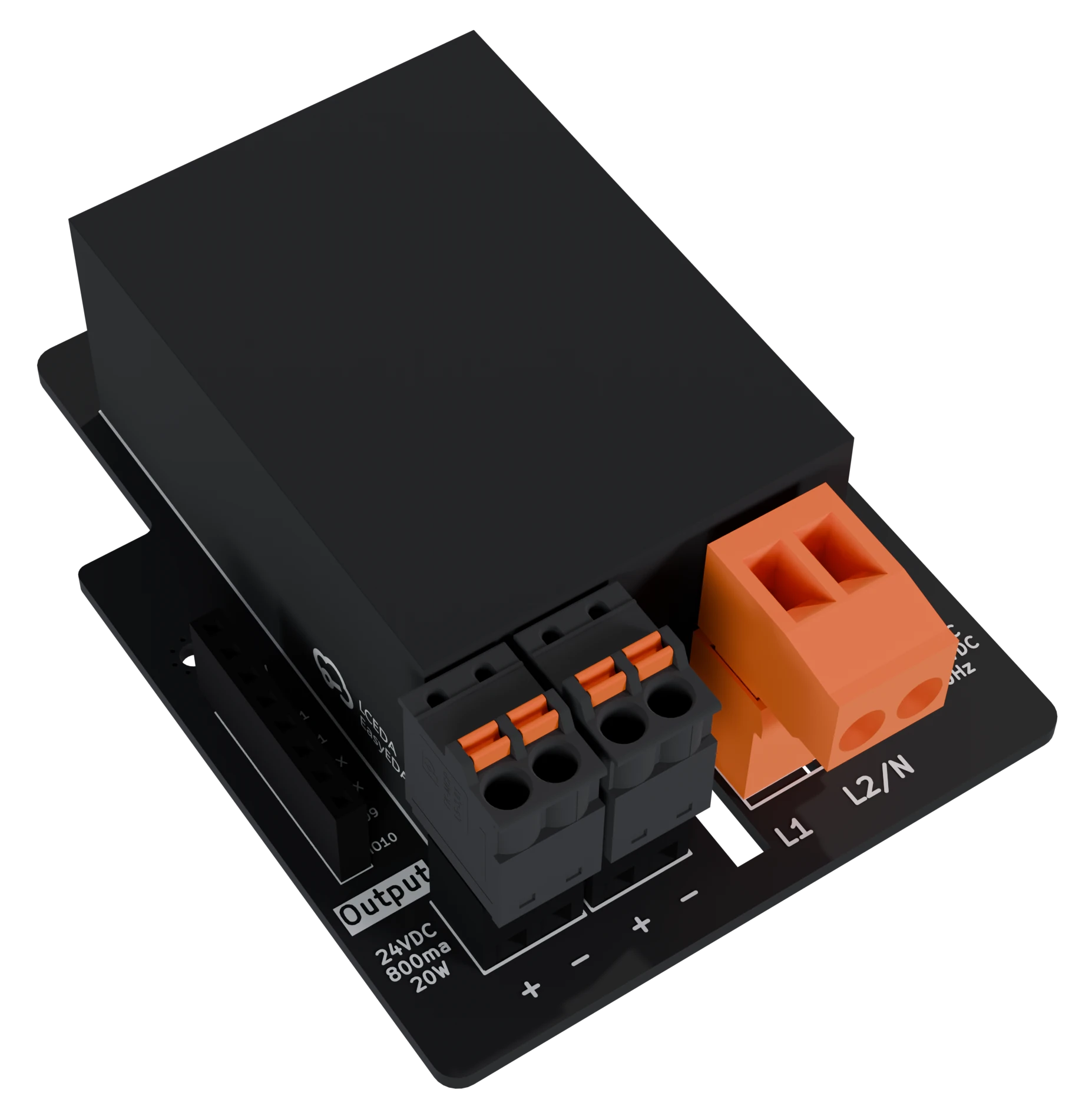
Isolated mains power supply hat for the ModBee Node-UIO. It turns 85–500 VAC or 100–700 VDC into 24 VDC at up to 800 mA. That powers the Node-UIO through the hat header and leaves two output terminals for field devices.
[!WARNING]
Mains voltage. The input terminals carry up to 500 VAC or 700 VDC. Install, wire and maintain this hat only if you are qualified and authorised to do electrical work where you live. Follow your local wiring rules (AS/NZS 3000 in New Zealand and Australia). Mount the assembly in an enclosure that keeps live parts out of reach, and isolate the supply before working on it.
Power module
The hat is built around the HIECUBE AP24N20-HV, an encapsulated 20 W AC-DC module from the AP-20W series. The figures below come from the manufacturer's datasheet. Unless noted, they are measured at 220 VAC input and 25 °C ambient.
| Parameter | Value |
|---|---|
| Input voltage | 85–500 VAC, 50/60 Hz, or 100–700 VDC |
| Input current | < 400 mA at 110 VAC, < 150 mA at 220 VAC |
| Power factor | < 0.58 |
| Start-up time | < 200 ms |
| Output | 24 VDC, 800 mA, 20 W |
| Load regulation | ±0.4 % |
| Efficiency | 86 % typical |
| Recommended load | 20–70 % of rated power at 25 °C |
| Switching frequency | 65 kHz |
| Isolation | 3000 VAC input to output for 1 minute, safety class II |
| Short-circuit protection | Continuous, self-recovering |
| Overload protection | Above 150 % load, self-recovering |
| Over-temperature protection | Module surface at 80 °C (±4 °C) |
| EMC | EN 55032 Class B conducted and radiated emissions; ESD ±4 kV contact, ±8 kV air |
| Operating temperature | −40 to +70 °C |
| Derating | Input below 100 VAC; ambient below −25 °C or above 40 °C |
| Cooling | Natural convection |
| Size, weight | 49 × 36 × 22.5 mm, 76 g |
Datasheet: LCSC C668103
Circuit
- J3 (orange): AC or DC input to the module.
- F1: 1 A resettable fuse on the 24 V output.
- C1–C3 (100 nF, 1 µF, 10 µF): output decoupling.
- D2: power LED.
- J4, J5 (black): two identical 24 V outputs, wired in parallel.
- D1: Schottky diode from the 24 V output to the hat header V_IN pin, which feeds the Node-UIO's supply input. The diode stops a supply connected to the Node-UIO from back-feeding the hat.
The hat uses only V_IN (J2 pin 3) and GND on the hat header. It does not use GPIO9, the UART, I2C or RS485. Those signals pass through for hats stacked above. See the hat connector pinout.
Connectors
J3 – input
| Pin | Silkscreen | Module pin |
|---|---|---|
| 1 | L1 | AC(L): line, or DC + |
| 2 | L2/N | AC(N): neutral or second line, or DC − |
J4, J5 – 24 VDC output
| Pin | Silkscreen | Signal |
|---|---|---|
| 1 | − | 0 V |
| 2 | + | +24 VDC |
The 800 mA rating is shared by J4, J5 and the Node-UIO, including anything the Node-UIO powers from its supply.
Input protection
The datasheet requires an input fuse. Use a safety-approved, slow-blow (time-delay) fuse. The manufacturer's reference circuit uses 2 A, 250 VAC. A slow-blow fuse rides through the inrush current while the module's input capacitor charges. A fuse rated too high will not protect the wiring or the module.
- The fuse and its holder must be rated for at least the supply voltage. For any supply above 250 VAC, a 250 VAC fuse is not suitable.
- When the hat is connected line to line, both input conductors are live. Protect each one, and use a two-pole isolator so both lines switch off together.
Line-to-line connection
On a 230/400 V three-phase system, the hat can be connected between two phases: 400 VAC is inside the module's 85–500 VAC range. The hat has two input terminals, so it always connects to one phase pair. Protect and isolate both lines as described above.
On 480 V systems, normal supply tolerance can push the voltage above the module's 500 VAC maximum. This hat is not suitable for them.
Noisy supplies
The module has a built-in EMC filter, which is enough for most installations. For harsh supplies, the datasheet gives an enhanced reference circuit with an inrush NTC (10D-11), an X capacitor (0.2 µF, 630 VAC), a common-mode choke, Y capacitors and an input varistor. Size these parts from the datasheet for your supply voltage.
Getting started
- Isolate the supply.
- Fit the hat to the Node-UIO with stacking headers. The 24 V reaches the Node-UIO through J2 pin 3 (V_IN).
- Wire a fused, isolatable supply to J3: L1 and L2/N.
- Connect field loads to J4 and/or J5 if needed. Keep the total current under 800 mA.
- Close the enclosure and switch the supply on. The power LED lights.
Schematic
schematics/modbee-hat-ps-acdc.pdf