
ModBee Node UIO board library
Board support for the ModBee Node UIO, an ESP32-S3 industrial I/O module for
35 mm DIN rail.
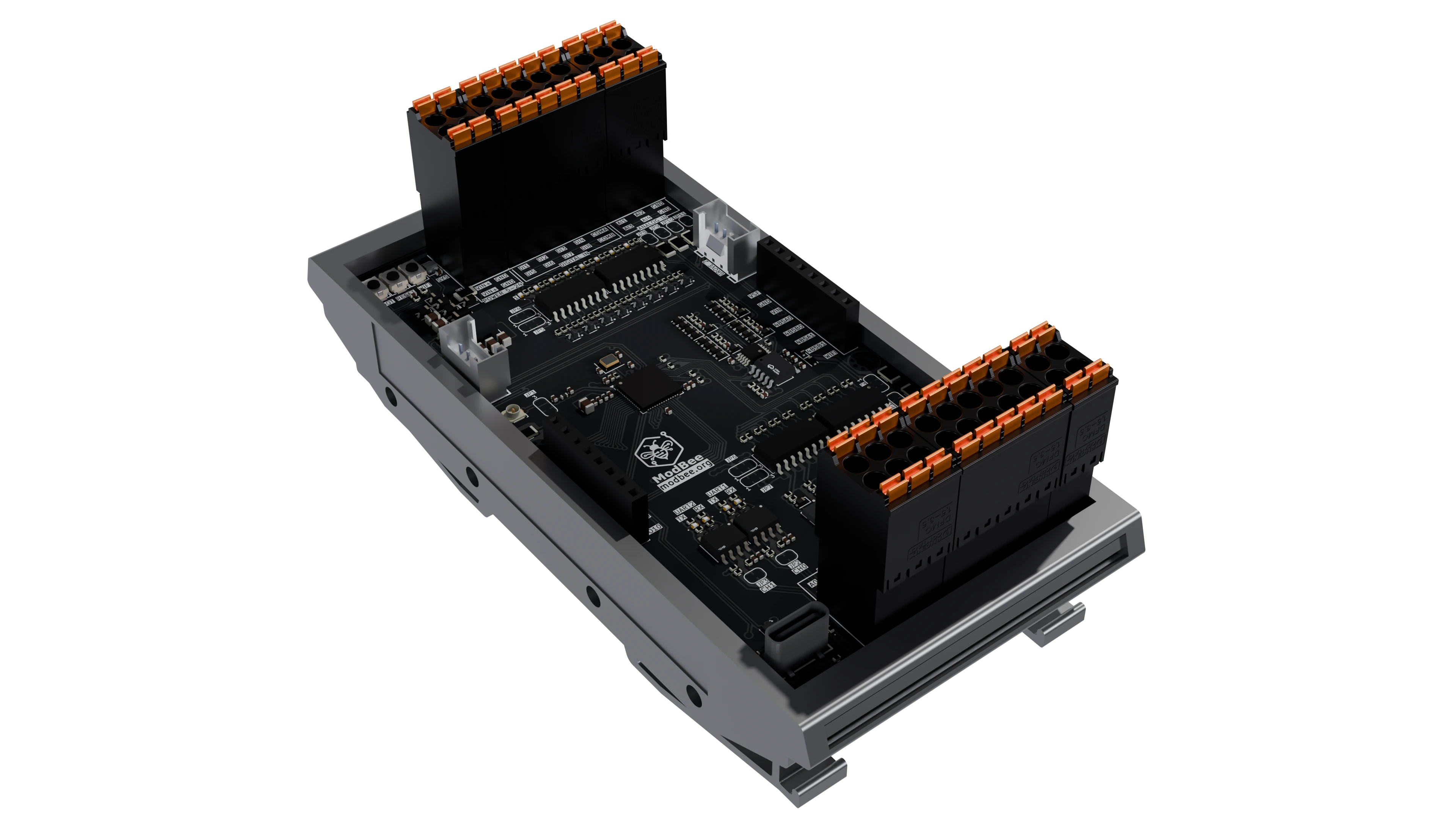
Hardware only: digital and analog I/O, pulse counting, the HAT power enable,
the button and status LED, Wi-Fi bring-up, sleep and wake, and the I2C
expansion bus. No communication protocol is built in. Modbus, the ModBee
protocol and anything else run alongside as their own libraries.
The board
| Microcontroller | ESP32-S3FH4R2, up to 240 MHz, 4 MB flash, 2 MB PSRAM |
| Digital inputs | 8, 5-24 V DC, opto-isolated, two groups of four with separate commons |
| Digital outputs | 8, 5-24 V DC, opto-isolated high-side (sourcing) MOSFET; 100 mA per output from the board supply, 500 mA with a separate supply |
| Analog inputs | 4, ADS1115 16-bit; 0-20 mA as shipped, 0-10 V per channel by solder bridge |
| Analog outputs | 2, GP8413 15-bit; 0-10 V as shipped, 0-20 mA per channel by solder bridge |
| Serial | 2 x RS485 |
| Expansion | 2 x Grove I2C (3.3 V), two 8-pin stackable HAT headers |
| Power | 5-24 V DC. USB-C powers the logic only; the analog outputs need at least about 9 V |
| Mounting | 35 mm DIN rail, 118 x 58 x 45 mm |
Whether an analog channel measures or drives voltage or current is a solder
bridge, not a setting. docs/HARDWARE.md has the pinouts,
the GPIO map, the power rails and every solder bridge, all taken from the
schematic.
Using it
#include <NodeUioAPI.h>

void setup() {
  uio().begin();
  uio().setInputRange(0, UIO_CURRENT);   // AI01 as shipped: 0-20 mA
  uio().setOutputRange(0, UIO_VOLTAGE);  // AO01 as shipped: 0-10 V
}

void loop() {
  uio().update();

  bool on = false;
  uio().digitalIn(0, on);
  uio().setDigitalOut(0, on);

  float milliamps = 0.0f;
  uio().analogIn(0, milliamps);
  uio().setAnalogOut(0, milliamps / 2.0f);   // 0-20 mA in, 0-10 V out
}
Everything goes through one class. docs/API.md is the
reference, and examples/NodeUioBasic is a complete sketch.
With OpenPLC
The OpenPLC function blocks for this board live in
modbee-openplc. They wrap this
library, so a program and a sketch see the same behaviour.
Building
PlatformIO, from this directory, builds the example:
pio run -e lolin_s3_mini
To use the library in your own project, see
Installing in the repository README.
Layout
src/
  NodeUioAPI.{h,cpp}        the public interface
  NodeUioTypes.h            enumerations, limits and scaling
  NodeUioBoard.{h,cpp}      the driver behind it
  NodeUioExpansion.{h,cpp}  the I2C expansion module framework
  NodeUioPulse.h            pulse count to rate
  lib/                      vendored drivers: ADS1X15, GP8XXX
examples/  docs/  schematics/  images/
src/ is the include root, so a vendored driver is reached as
#include <lib/ADS1X15/ADS1X15.h>.
Licence
AGPL-3.0, see LICENSE. The vendored drivers keep their own MIT
licences, in their folders: ADS1X15 by Rob Tillaart, and GP8XXX, a modified
copy of DFRobot's DFRobot_GP8XXX.